|


| |
|
Circuit breakers |
|
Definition:
Circuit breaker:- A manually (or remote) operated device capable of making,
carrying and breaking its rated current under specified normal circuit conditions and also automatically breaks
(opens) a
circuit under specified over current
conditions such as overload and short circuit currents.

|
Circuit breaker
technolgies:
- Thermal and or magnetic:
- Hydraulic magnetic:
- Electronic,
|
|
Acronyms:
***See page
acronyms for a comprehensive list
| SCPD |
Short-Circuit Protective Device |
| |
|
| MCB |
Miniature circuit breaker - 0.5 o 125Amp, |
| MCCB |
A circuit breaker having a supporting housing of moulded
insulating material forming an
integral part of the circuit breaker (IEC 947-2). |
| ACB |
Air circuit breaker |
| In |
Nominal trip current indicated on CB. |
|
| Zero current circuit
breakers: See acronyms and definitions |
| Energy limiting
circuit breakers: See acronyms and definitions |
Concept of a
current limiting circuit breaker:
Interrupting
short-circuit current:-
As an example, let us consider a quick acting, current limiting circuit
breaker a
described previously.
To limit the short-circuit current already at its initiation, the main
contacts must be opened by the striker within a few milliseconds.
A very fast acting device may need less than 1ms for this. An
arc is struck immediately, which driven towards the arc chamber, delivers a
high arc voltage.
As a simplification,
the arc
voltage can be considered as an equivalent additional resistance connected
in
series to the current circuit which immediately limits the rising
short-circuit
current.
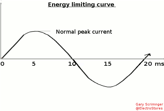
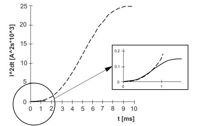
| What is this "let through energy" definition in terms
of math: 1 joule per second equals 1 watt
The short circuit current curve look like a short parabola and that
is defined as x2 so:
E= ∫i2 dt - meaning it is the area below the curve.
According to the calculus rule it is calculated as I2t joules.
or also:
Power = VI = I2R in watts
and so
Electrical energy= Power(watts) x time = (I2 x R) x time (seconds) in
Joules.
but what if the R is so small compared to I one can ignore it, then
Energy = I2t joules
***Maybe the mathematicians out there will kill me for this but it
is how I understand it.
|
---------------=============-------------
--------------===========---------------
---------=============----------
|
| |
| In depth look at the
tripping curve:
selective short-circuit (S),
---------===========---------
-----------==========-------- |
| |
|
Tripping curves:
----------------- |
|
Analysis of a short circuit:-
Terms to DIN EN 60 909-0 VDE 0102/0103 for
short-circuit currents in three-phase systems
Peak short-circuit current (ip): The
maximum permissible instantaneous value of the anticipated short
circuit current.
Note: The value of the peak short-circuit current
depends on the moment when the short-circuit
occurs. Calculation of the peak short-circuit
current in a three-pole short-circuit refers to the
conductor and the moment at which the maximum
possible current occurs.
Sustained short-circuit current Ik: The
effective value of the short-circuit current which is retained once all
transient reactions have decayed.
Initial symmetrical short-circuit current
Ik˝
The effective value of the symmetrical AC component of an anticipated
short-circuit current at the moment of occurrence of the short-circuit, if the
short-circuit impedance retains the value at the time zero.
Illustration: Progression of the short-circuit
current over time with remote short-circuit (diagrammatic representation).
Ik˝ Initial symmetrical short-circuit current
ip Peak short-circuit current
ik Sustained short-circuit current
iDC Decaying DC component of the short-circuit current
A Initial value of DC component iDC
Thermal short-circuit current I
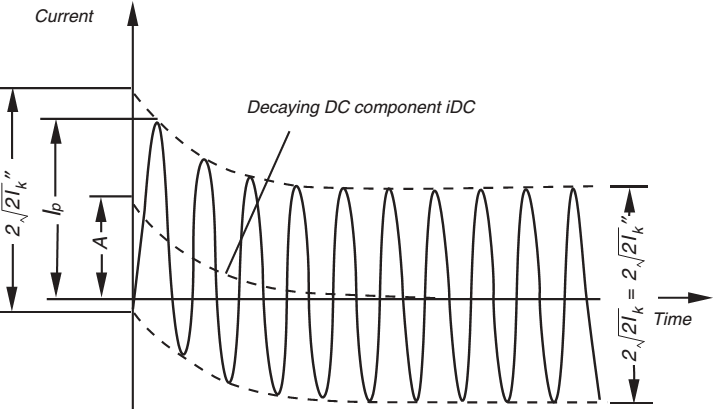
-------=======----------
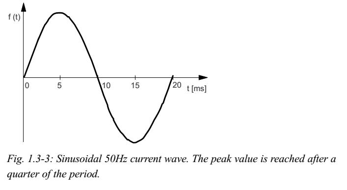
The short-circuit current reaches its peak value
after a quarter of the sinusoidal period, which is 5 milliseconds for 50Hz
supply (4.2ms in the case of 60Hz as in the USA), assuming that the current is
symmetrical, i.e. initiated at a current zero. This is to be prevented.
|
|
Summary: circuit breaker as load break switch |
| |
|
Below is the different processes: How shall a circuit
breaker be rated(selected):
|
How is it
selected for overload current protection
| SANS10142: 6.7.x |
IEC 60364 |
NEC Article 230.42 |
|
SANS give
pre-requisites for components first.
For a circuit breaker it must, at a specific voltage
(considering the circuit power factor) and the fault current
equalling its rated breaking capacity or lower be capable of breaking
the circuit. gs
5.1.3 - EFP
5.2.5 - protection
equipment
7.13 hiV apparatus
2.2.1 South African standards
SANS 152 (SABS 152), Low-voltage air-break switches, air-break
disconnectors, air-break switch-disconnectors
SANS 156 (SABS 156), Moulded-case circuit-breakers.
SANS 556-1, Low-voltage switchgear – Part 1: Circuit-breakers.
SANS 767-1 (SABS 767-1), Earth leakage protection units – Part 1: Fixed
earth leakage protection circuit-breakers.
SANS 61008-1/IEC 61008-1, Residual current operated circuit-breakers
without integral overcurrent protection for household and similar uses (RCCBs)
– Part 1: General rules.
SANS 3.71
short-circuit protective device SCPD device intended to protect a circuit or p
A
|
|
An interesting note I found in NEC article 100 definitions: was that the automatic means does
not have to be an integral part of the circuit breaker - that is a
surprise. gs UL 508, Industrial control
equipment.
|
|
6.7 Protection
6.7.1 Overcurrent protection
NOTE The term over current protection includes both overload protection
(see 6.7.2) and short-circuit protection (see 6.7.3).
6.7.1.1
Each protective device shall have a rated current that does not exceed
the lowest of the current-carrying
capacities of any of the conductors of the circuit and shall have a
minimum short-circuit rating of 2,5 kA.
6.7.2 Overload protection
6.7.2.1
Overload protection:
The rated current of the overload protective device shall not
exceed the current-carrying capacity of the conductor it protects,
except in the case of circuits in which the presence of overload
protection could create a dangerous situation, such as in circuits for
lifting magnets
BTW: No mention of the component current
ratings?gs
Table 6.26
Maximum
circuit breaker rating(A)
|
Cable size mm2 |
| 10 |
1 |
| 16 |
1,5 |
| 25 |
2,5 |
PS: Don't make the mistake of
thinking this is all to it, depending on what the circuit is used for
the dictation changes. gs
|
4.4.4.1
Reference:- ABB Comparison of
tripping characteristics
for miniature circuit-breakers
For protection against overload, the
protective device must be selected based on the current carrying
capacity
Ib
≤
In ≤
Iz (standard)
Idesign
≤
Icb ≤
Icable (gs)
and
I2
≤
1.45 x Iz (standard)
Ioperation
≤
1.45 x Icable (mine)
Ib= Design current of a circuit
In= Rated current of the protective
device
Iz= Current carrying capacity of the
cable in accordance with IEC/HD 60364-5-52
I2 = Current ensuring effective
operation in the conventional time of the protective device
IEC 60364-4-43h
|
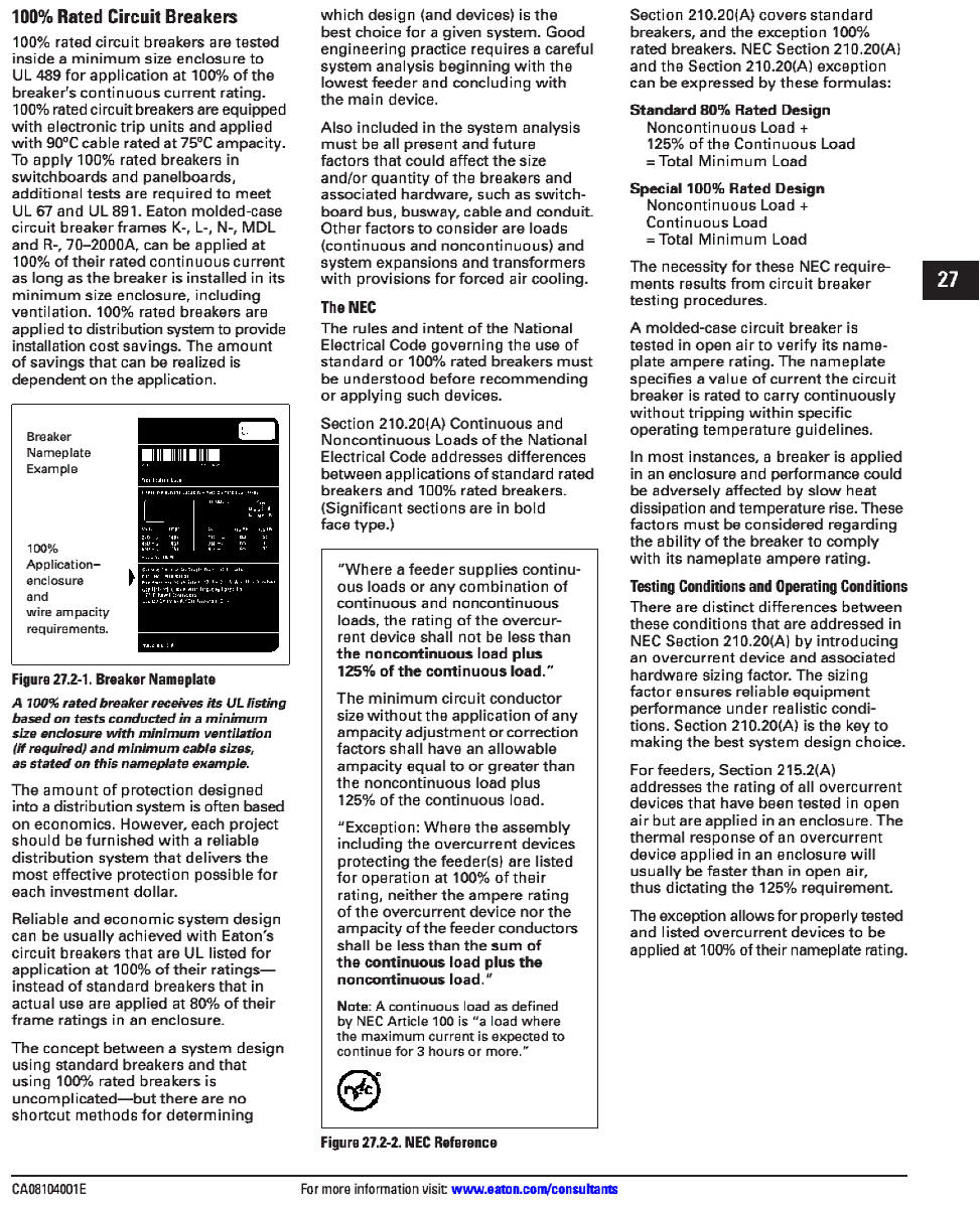
Where a feeder supplies continuous loads or any combination of
continuous and non-continuous loads, the rating of the
over current device shall not be less than the non-continuous load plus
125% of the continuous load.
Exception: Where the assembly including the overcurrent
devices protecting the feeder(s) are
listed for operation at 100% of their rating, neither the ampere rating
of the overcurrent device nor the ampacity of the feeder conductors
shall be less than the sum of the continuous load plus the noncontinuous
load.
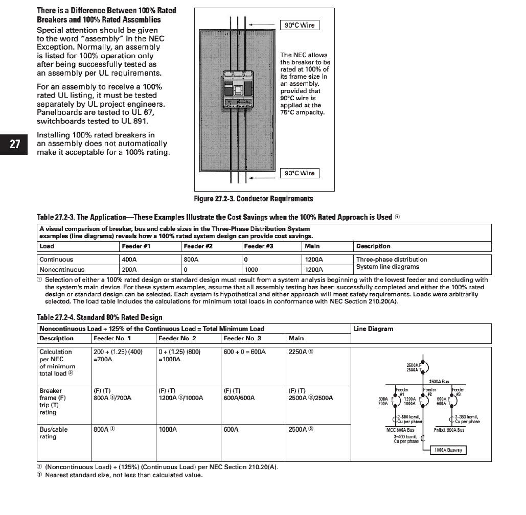
Only breakers listed for 100% application,
and so labelled can be applied under the exception (for example loads
Frame and R Frame 140G’s that are specifically marked and rated 100%).
Breakers without a 100% application listing and label are
applied at 80% of rating
I could not find above in NEC 2011 - so I struck it through.
This is in 2011:II. Branch-Circuit Ratings
210.19 Conductors — Minimum Ampacity and Size.
(A) Branch Circuits Not More Than 600 Volts.
(1) General. Branch-circuit conductors shall have an ampacity not less
than the maximum load to be served.
Where a branch circuit supplies
continuous loads or any combination of continuous and noncontinuous
loads, the minimum branch-circuit conductor size, before the application
of any adjustment or correction factors, shall have an allowable
ampacity not less than the noncontinuous load plus 125 percent of the
continuous load.
Exception: If the assembly, including the overcurrent devices protecting
the branch circuit(s),
is listed for operation at 100 percent of its
rating, the allowable ampacity of the branch circuit conductors
shall be permitted to be not less than the sum of the continuous load
plus the noncontinuous load.
Informational Note No. 1: See 310.15 for ampacity
ratings
of conductors.
Informational Note No. 2: See Part II of Article 430 for
minimum rating of motor branch-circuit conductors.
Informational Note No. 3: See 310.15(A)(3) for temperature limitation of
conductors. Meaning:
For <=600V circuits
Icable>=Iload
For assembly NOT listed for 100%
operation:
***Not considering adjustment factors.
Mixed loads(Non-Cont and Cont) Icable>Sum of Inoncont
+125%Icont
For assembly listed for 100%
operation:
Mixed loads(Non-Cont and Cont) Icable > Sum of
Inoncont + Icont
=============
(B) Overcurrent Devices Rated 800 Amperes or Less.
The next higher standard overcurrent device rating (above the ampacity
of the conductors being protected) shall be permitted to be used,
provided all of the following conditions are met:
(1) The conductors being protected are not part of a
branch circuit supplying more than one receptacle for cord
and-plug-connected portable loads.
(2) The ampacity of the conductors does not correspond
with the standard ampere rating of a fuse or a circuit
breaker without overload trip adjustments above its rating (but that
shall be permitted to have other trip or
rating adjustments).
(3) The next higher standard rating selected does not
exceed 800 amperes.
(C) Overcurrent Devices Rated over 800 Amperes.
Where the overcurrent device is rated over 800
amperes, the ampacity of the conductors it protects shall be equal to or
greater than the rating of the overcurrent device defined in
240.6.
Meaning: Except if a small
conductor (the lord alone knows what this is) If <800amp one an select a
one size higher fuse - as long as such size is <800Amp.
For higher the 800Amp it must be
same as cable or by some 240.6
|
|
b) Opening under overload conditions
1) Instantaneous or definite time-delay operation
The release shall cause tripping of the circuit-breaker with
an accuracy of i10 O/. of the tripping current value of the current setting
for all values of current setting of the overload release.
2) Inverse time-delay operation. Conventional values for
inverse time-delay operation are given in table 6.
|
60 947-2
Opening under overload conditions
7.2.1 .2.4 : b
1) Instantaneous or definite time-delay operation
The release shall cause tripping of the circuit-breaker
with an accuracy of i10 O/. of the tripping current value of the
current setting for all values of current setting of the overload
release.
meaning: CB accuracy <
+-10% of for all values of Ir (gs)
2) Inverse time-delay operation Conventional values for
inverse time-delay operation are given in table 6.
Table 6
simply says
for
lower/equal to 63Amps - at 1.05In circuit must trip after 1 hr only, if
then raised to 1.3In it must trip ONLY within 1hr
At
bigger then 63amps it becomes 2hr
They talk
about this time as conventional time.
At the reference temperature (see 4.7.3) and at 1,05 times the current
setting (see 2.4.37 of Part 1), i.e. with the conventional
non-tripping current (see 2.5.30 of Part 1), the opening release
being energized on all phase poles, tripping
shall not occur in less than the conventional time (see 2.5.30 of
Part 1) from the cold state, i.e. with the circuit-breaker at the
reference temperature.
Meaning: 1.05Ir @Tref no tripping
within 1hr (gs) at cold state
Moreover, when at the end of the conventional time the
value of current is immediately raised to 1,30 times the current
setting, i.e. with the conventional tripping current (see 2.5.31 of Part
1), tripping shall then occur in less than the conventional time later.
Meaning: At 1.3Ir tripping must
occur in less than conventional time(gs) (conventiaonal time is that
In<63A->1hr and In>63Amp->2 hr)
------------
NOTE The reference temperature is the ambient air
temperature on which the time-current characteristic of the
circuit-breaker is based. 4.7.3
4:7:3:
Unless otherwise specified
– Non thermal overloads no change -5 “C to +40 ‘C;
-Thermal
overloads - reference temperature of +30 “C +- 2 “C. Manufacturer shall
provide variations data (see 7.2.1.2.4, item b)).
2:4:37: - and
2:5:30 could not find references |
|
| |
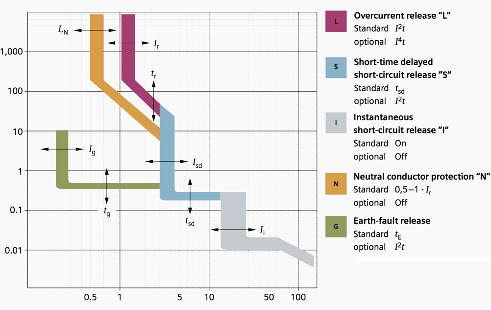
DEFINING THE TRIPPING CURVE
4.7.4 Tripping time
setting of over-current releases
1) Definite time-delay over-current releases
The time-delay of such releases is independent of the over-current.
The
tripping time setting shall be stated as the duration in seconds of the
opening time of the circuit-breaker, if the time-delay is not
adjustable, or the extreme values of the opening time~ if the time delay
is adjustable.
2) Inverse time-delay over-current releases
The time-delay of such releases is dependent on the over-current.
The time/current characteristics shall be given in the form of curves
supplied by the
manufacturer.
These shall indicate how the opening time, starting from
the cold state, varies with current within the range of operation of the
release.
The manufacturer shall indicate, by suitable means,
the tolerances applicable to these curves.
These curves shall be given for each extreme value of
the current setting and, if the time
setting for a given current setting is adjustable, it is recommended
that they be given in
addition for each extreme value of the time setting.
NOTE It is recommended that the current be plotted as
abscissa and the time as ordinate, using logarithmic scales.
Furthermore, in order to facilitate the study of
co-ordination of different types of over-current protection,
!t is
recommended that the current be plotted as multiples of the setting
current and the time in seconds on the standard graph sheets detailed in
5.6.1 of IEC 60269-1 and in figures 4(l), 3(11) and 4(11) of IEC
60269-2-1. |
|
| |
|
|
-------------------
|
|
-------------============------------
Circuit breaker
Reference temperature:
| |
lS/lEC 60947-2:2003 |
|
| |
Unless otherwise specified – the operating value of
overload releases other than those of the thermal type is independent of
the ambient air temperature within the limits of -5 “C to +40 ‘C;
for releases of the thermal type, the values stated are
for a reference temperature of +30 “C, +- 2 “C. The manufacturer shall be
prepared to state the influence of variations in the ambient air
temperature (see 7.2.1.2.4, item b)).
Meaning:
4:7:3: Unless otherwise specified
– Non thermal overloads no change -5 “C to +40 ‘C;
-Thermal
overloads - reference temperature of +30 “C +- 2 “C. Manufacturer shall
provide variations data (see 7.2.1.2.4, item b)). |
|
--------------=============------------ |
|
And the impedance?
| BS EN 60947-2 - calculating Zs |
|
|
In this case Zs is determined from the basic equation:-
Zs Ia≤ UoCmin– which transposes to: - Zs≤ ((UoCmin)/Ia) where:-
Uo is the nominal voltage to earth.
Ia is the current required to achieve the disconnection time as given in
the Regulations.
Cmin is the minimum voltage factor to take account of voltage
variations depending on time and place, changing of transformer taps and
other considerations.
NOTE: For a low voltage supply given in accordance with the
Electricity Safety, Quality and Continuity. Regulations 2002 as amended,
Cmin is given the value 0.95.
|
|
|
|
| Art: 110 |
|
And short circuit currents:
| SANS10142: 6.7.3 |
IEC |
NEC 2011 Art 110 |
6.6.1.15 Switchgear shall be fully rated
for withstanding the prospective
short-circuit current that could occur at that point in the system,
unless
series-connected (cascaded)
systems are applied in accordance with
6.7.4.6.6.1.16 Where the prospective fault
level of the supply cannot be determined, a fault current meter may be
used (see 8.5.2).
6.6.1.17 All
disconnecting devices in a distribution board
a) shall be protected by a fully rated short-circuit protective device,
and
b) when used in combination with a short-circuit protective device (see
6.7.4), shall have a conditional
short-circuit current rating (see 3.22.1)
appropriate to its condition of installation, but of not less than 2,5
kA
Short-circuit protection
6.7.3.1 At its point of installation, a short-circuit protective device
shall be capable of breaking any over current up to the value of the
prospective short-circuit current. (See also 6.7.4 on cascaded systems.)
|
----------IEC 60 364----------
4.4.5.5.1 The rated breaking capacity shall be not
less than the prospective maximum short-circuit current at the place
of its installation, except cascading.
CB kA> circuit shortcircuit at
point(gs)
4.4.5.5.2 For cables and insulated conductors, all
current caused by a short-circuit occurring at any point of the
circuit shall be interrupted in a time not exceeding that which
brings the insulation of the conductors to the permitted limit
temperature.
Meaning: Tshort max < Cable temp rise to limit
time (at that current(gs)
For
operating times of protective devices <0.1 s where asymmetry
of the current is of importance and for current-limiting devices
k2xS2 shall be greater than the value of the
let-through energy (I2t) quoted by the manufacturer of the
protective device.
Meaning: if Tshort<0.1 Table 43A
applies (special I think) (gs)- We depend on let through energy of
CB
For short-circuits of
duration up to 5 s, the time t, in which a given
short-circuit current will raise the insulation of the conductors
from the highest permissible temperature in normal duty to the limit
temperature can, as an approximation, be calculated from the
formula:
t = (k * s/l)Squared
t = time it will take to
reach this max (sec)
S is the cross-sectional area, in mm2;
I is the effective short-circuit current, in A, expressed as an
r.m.s. value;
k is a factor taking account of the resistivity, temperature
coefficient and heat capacity of the conductor material, and the
appropriate initial and final temperatures. For common conductor
insulation, the values of k for line conductors are shown in Table
43A.
Meaning: Ensure t is quick enough (ONLY
applicable if Tshort <=5sec)
---Additionally: IEC 60947-2: for CB---
7.2.5 Ability to make and break under short-circuit
conditions
Subclause 7.2.5 of Part 1 applies with the following
amplifications:
The rated short-circuit making capacity shall be in
accordance with 4.3.5.1(Rated short circuit making capacity) and
4.3.5.3 (Standard relationship between short-circuit making and breaking
capacities and related power factor, for a.c. circuit-breakers)
The rated short-circuit breaking capacity shall be in
accordance with 4.3.5.2
The rated short-time withstand current shall be in
accordance with 4.3.5.4
NOTE It is the manufacturer’s responsibility to ensure that
the tripping characteristic of the circuit-breaker IS compatible with the capability of the circuit-breaker to withstand the
inherent thermal and electrodynamlc stresses
---============-----
and the association shall comply with the requirements of 7.2.1.2.4, item
a)
-----===========----
7.2.1 .2.4 Opening by over-current releases a)
Opening under short-circuit conditions
The short-circuit release shall cause tripping of the
circuit-breaker with an accuracy of 20%
of the tripping current value of the current
setting for all values of the current setting of the short-circuit current release.
Where necessary for over-current co-ordination (see
2.17), the manufacturer shall provide Information (usually curves)
showing. maximum cut-off (let-through) peak current (see 2.5 19 of Part
1) as a function of prospective current (r, m.s. symmetrical);
— /2t characteristics (see 2.18) for circuit-breakers of
utilization category A and, if
applicable,
B for circuit-breakers
with instantaneous override (see note to 8.3.5).
Conformity with this information may be checked during
the relevant type tests in test
sequences II and Ill (see 8.3.4 and
8.3.5).
NOTE It may be possible to provide other forms of data
to verify co-ordination characteristics of circuitbreakers, for example,
tests on combinations of short-circuit protective devices.
Rated short-time withstand
current (Icw)
The rated short-time withstand
current of a circuit-breaker is the value of short-time withstand
current assigned to that circuit-breaker by the manufacturer under
the test conditions specified In 8.3.6.2.
For a.c., the value of this
current is the r.m.s value of the a,c. component of the prospective
short-circuit current, assumed constant during the
short-time delay.
The short-time
delay associated with the rated short-time withstand current shall
be at least 0,05 s,
Preferred values being as
follows:
0,05 –0,1 –0,25–0,5–1 S
The rated short-time withstand
current shall be not less than the appropriate values shown in table
3
Table 3- Minimum values of
rated short-time withstand current
In = CB rated current
In <2500 ->12xIn or 5 kA,
whichever is the greater
In >2500 ->30 kA
-------------============--------
|
110.9 Interrupting Rating.Equipment intended to interrupt current at
fault levels shall have an interrupting ratin
not less than the nominal circuit voltage and the current thais
available at the line terminals of the equipment.
Equipment intended to interrupt current at other than fault levels
shall have an interrupting rating at nominal circuit voltage not
less than the current that must be interrupted.
110.10 Circuit Impedance, Short-Circuit Current
Ratings, and Other Characteristics.
The overcurrent protective devices, the total impedance, the equipment shortcircuit current ratings, and other characteristics of thecircuit to be protected shall be selected and coordinated to
permit the circuit protective devices used to clear a fault to
do so without extensive damage to the electrical equipment
of the circuit.
This fault shall be assumed to be either between two or more of the circuit conductors or between an
circuit conductor and the equipment grounding conductor(s) permitted in 250.118.
Listed equipment applied in
accordance with their listing shall be considered to meet the
requirements of this section.
====== 230.208 Protection
Requirements. A short-circuit protective device shall be
provided on the load side of, or as an integral part of, the service
disconnect, and shall protect all
ungrounded conductors that it supplies.
The protective device shall be capable of
detecting and interrupting all values of current, in excess of its
trip setting or melting point, that can
occur at its location.
A fuse rated in
continuous amperes not to exceed three times the ampacity of the
conductor,
or a circuit breaker with a
trip setting of not more than six times the ampacity of the
conductors, shall be considered as providing the required
short-circuit protection. |
|
| Found his
table from Panel design Rittal - to be completed
------------=============-----------
|
Circuit breaker
Utilisation categories
| |
IEC 60947.2: 4.4: |
|
| |
Table 4- Utilization categories
Category ACircuit-breakers not
specifically intended for selectivity under short-circuit conditions with respect to other short-circuit
protective devices in series on the load side, i.e. without an intentional
short-time delay provided for selectivity under short-circuit conditions,
and therefore without a short-time withstand current rating according to 4.3.5.4.
Category B
Circuit-breakers specifically intended for selectivity
under short-circuit conditions with respect to other short-circuit
protective devices in series on the load side, i.e. with an intentional short-time
delay (which may be B adjustable), provided for selectivity under
short-circuit conditions. Such circuit-breakers have a short-time withstand current
rating according to 4.3.5.4.
NOTE Selectivity is not necessarily ensured up to the
ultimate shortcircuit breaking capacity of the circuit-breakers (for example
in the case of operation of an instantaneous release) but at least up to the
value specified in table 3.
table 11 (see 8.3.2.2.4 and 8,3.2,2.5),
NOTE 2 Attention is drawn to the different requirements
for the minimum required percentage of lc~ for utilization categories A and B, in accordance with table
1.
NOTE 3 A circuit-breaker of utilization category A may
have an intentional short-time delay provided for selectivity under conditions other than those of short
circuit, with a short-time withstand current less than that according to table 3. In that case, the tests include test sequence
IV (see 8.3.6) at the assigned short-time
|
|
| |
4.3.5.4: |
|
| |
Table 11 |
|
| |
Hager: •Ref:Electricians handbook courtesy of
Larson and Toubro - India:
*I dont have 60 898
IEC classifies MCBs into three category depending upon their “Quality
of current
limiting” & let through energy of a circuit breaker on short circuits.
Permissible let to energy values for circuit breakers with rated current
up to and including 16A as per
EN60898 are:
Class 1 No limitation
Class 2 290 kA²S
Class 3 84 kA²S -
*All Hager mcb are class 3
|
|
|
| ------------=============------------ |
|
Where must it be installed?
| south Africa
SANS10142: 6.7.1.1 |
Europe + IEC 60364
|
USA+ UL489
UL1077
|
Canada
CSA c22.2 No 5.02CSA c22.2 No 235-04
|
|
china GB 14048-2 |
| 6.7.2.2 Overload must be installed at point of conductor
reduction OR - with a switch/disconnector OR earth-leakage unit that
requires overload protection. UNLESS
The over current device can sit anywhere in the cable as long as no
connections to/from it
AND
entire length protected against shorts circuit OR
cable shorter then 5mtrs
not near flammable materials
not likely to cause humans harm
I spent a lot of time trying to get
to grips with this - I get this feeling this commission could not get
consensus the matter of "anywhere in the cable"...thus the strange
additions. Flammable and human safety? Really?
Now the challenge: Overload unit
can be anywhere in the cable but the whole cable must be short circuit
protected?
Mechanical protection or another
electrical component? Are
we confusing motor overload protection with cable / reticulation
protection here? |
G-2 CASES WHERE SHORT-CIRCUIT PROTECTION DOES NOT
NEED TO BE PLACED AT THE ORIGIN OF BRANCH CIRCUIT With
reference to 4.4.5.2.1and Fig. G.1, short-circuit protective device P
2may be moved up to 3 m from the origin (O) of the branch circuit (S2)
provided that there is no other connection or socket-outlet on this
length of the branch circuit, and in the case of 4.4.5.2.1
the risk of short-circuit, fire and danger to persons is reduced to a
minimum for this length.
but:
4.4.4.2 Position of devices for overload protection
4.4.4.2.1 A device ensuring protection against overload shall be placed
at the point where a
change, such as a change in cross-sectional area, nature, method of
installation or in constitution,
causes a reduction in the value of current-carrying capacity of the
conductors, except where
4.4.3.2.2and 4.4.3.3 apply.
4.4.4.2.2 The device protecting the conductor against
overload may be placed along the run of that conductor if the part of
the run between the point where a change occurs (in cross-sectional
area, nature, method of installation or constitution) and the position
of the protective device has neither branch circuits nor socket-outlet
circuits and fulfils at least one of the following two conditions:
a) it is protected against short-circuit current in accordance with the
requirements stated in 4.4.5;
b) its length does not exceed 3 m, it is carried out
in such a manner as to reduce the risk of shortcircuit to
a minimum, and it is installed in such a manner as to reduce to a
minimum the risk of
fire or danger to persons (see also 4.4.5.2.1).
NOTE: For installation according to a) see Figure F.1.
For installation according to b) see Figure F.2
. |
|
|
|
|
| |
|
|
|
|
|
| 6.7.2.3The overload protective device
may be installed at any point in the conductor run that it protects,
provided that
a) there is no branch circuit or socket-outlet between
the point where there is a reduction in the conductor's current-carrying
capacity and the point where the device is installed, and
b) the entire length of the conductor is protected against
short-circuit, or
c) the conductor is
1) of length not exceeding 5 m,
2) so installed as to minimize the risk of overload or fault in its
operating condition,
3) not near flammable materials, and
4) not likely to cause harm to a person in the event of a fault |
|
|
|
|
|
| Now short circuit protection is as plain
and simple as "installed at the point of reduction" - as it should be!
6.7.3.2 |
AND SHORT CIRCUITS?
4.4.5.2 Position of devices for short-circuit
protection A device ensuring protection against short-circuit shall
be placed at the point where a reduction in the cross-sectional area of
the conductors or another change causes a change to the current-carrying
capacity of the conductors, except where 4.4.5.2.1, 4.4.5.2.2or 4.4.5.3
applies.
4.4.5.2.1 The various cases stated in the following sub clause shall not
be applied to installations situated in locations presenting a fire risk
or risk of explosion and where special rules for certain
locations specify different conditions. The device for protection
against short-circuit may be placed other than as specified in 4.4.4.2,
under the following conditions.
In the part of the conductor between the point of
reduction of cross-sectional area or other change and the position of
the protective device there shall be no branch circuits nor
socket-outlet circuits
and that part of the conductor shall:
a) not exceed 3 m in length, and
b) be installed in such a manner as to reduce the risk of a
short-circuit to a minimum,
and so forth and so forth...
|
|
|
|
|
|
|
... |
|
Disconnection times -
protection devices and RCD Gary
The higher the value of Uc, the higher the rapidity of supply
disconnection required to provide protection (see Fig.
F7). The highest value of Uc that can be
tolerated indefinitely without danger to human beings is 50 V AC.
In DC the highest value of Uc that can be tolerated indefinitely without
danger is 120 V.
Disconnecting-time limits (IEC 60364-4-41)
Mine: 4.2.11.3.2.2
Fig. F7 – Maximum
disconnecting times (in seconds) for final circuits not exceeding 63 A
with one or more socket-outlets, and 32 A supplying only fixed connected
current-using equipment
| Uo (V AC) |
50 < Uo ≤ 120 |
120 < Uo ≤ 230 |
230 < Uo ≤ 400 |
Uo > 400 |
| System |
TN |
0.8 |
0.4 |
0.2 |
0.1 |
| TT |
0.3 |
0.2 |
0.07 |
0.04 |
Nota:
 | in TN systems, a disconnection time not exceeding 5 s is
permitted for distribution circuits, and for circuits not covered by
Fig. F7 |
| in TT systems, a disconnection time not exceeding 1 s is
permitted for distribution circuits and for circuits not covered by
Fig. F7 |
For human protection an RCCB
must have sensitivity of 30mA max and must trip within 40ms max at residual
current of 150mA tba gs
Nb: Must add the details of the standards
specifications on the actual tripping set point of an earth leakage
device.gs
*Ref: Hager QZD009 Protection devices cat. pg. D26
|
| IEC 60364 |
|
4.4.4.3 Omission of devices for
protection against overload
The various cases stated in this sub-clause shall not be applied to
installations situated in locations
presenting a fire risk or risk of explosion or where the requirements
for special installations and
locations specify different conditions.
4.4.4.3.1 General Devices for protection against
overload need not be provided:
a) for a conductor situated on the load side of a change in
cross-sectional area, nature, method of
installation or in constitution, that is effectively protected against
overload by a protective
device placed on the supply side;
b) for a conductor that is not likely to carry overload current,
provided that this conductor is
protected against short-circuit in accordance with the requirements of
4.4.4 and that it has neither branch circuits nor socket-outlets;
c) at the origin of an installation where the distributor provides an
overload device and agrees that it affords protection to the part of the
installation between the origin an d the main distribution point of the
installation where further overload protection is provided.
d) for circuits for telecommunications, control, signalling and the
like.
NOTE: For installations according to a), b) and d), see Fig. F.3.
|
|
| |
|
| |
|
|
|
Relevant standards and circuit breakers:
PS: This is a reference based on manufacturer material
referring to the different standards - Excuse if you are specialist and find
some discrepancy...just let us know - for this is always a work in progress
we would be a happy to oblige.
Standards references to circuit breakers:
| |
UL |
ANSI |
NEC |
CSA |
SANS |
IEC |
| Genl |
Alsocheck: The requirements for
overcurrent protection devices are for use in industrial cabinets
(Industrial Control Panels) anchored in the UL 508A
Mechanical engineering the NFPA 79 (Electrical
Standard for Industrial Machinery) and Safe on the North American market
-
|
|
Articles: 210 - Branch circuits
215 - Feeders
240 - Overcurrent Protection
430 - Motors, Motor Circuits, and Controllers
controllers, and m |
|
VC8035 -
VC8036 -
|
IEC 60947-2 (circuit breaker design and manufacturing)
IEC 60364, § 434.5.1 (electrical distribution network).
| IEC 947-4 - Circuit breakers with
motor protective characteristics |
|
| MCB |
UL1066 - LV AC and DC CB in Enclosures
|
- ANSI C37.13: IEEE Standard for Low-Voltage AC Power
Circuit Breakers Used in Enclosures
- ANSI C37.16: Low-Voltage Power Circuit Breakers and AC
Power Circuit Protectors.
Preferred Ratings, Related Requirements, and Application
Recommendations
- ANSI C37.17: American National Standard for Trip
Devices for AC and General
Purpose DC Low Voltage Power Circuit Breakers
|
|
|
|
| .60 898 |
|
| MCCB |
UL 489 - NEC -Branch circuit protection. MCCB. UL 489: Molded-Case
Circuit Breakers, Molded-Case Switches and Circuit
Breaker Enclosures
UL 489 MCCB: MCS(Molded Case Switches) & Circuit Breaker Enclosures.
| UL 489A - Branch circuit protection DC circuit breaker short circuit
protection in communications equipment. |
| UL1077 - Used in conjunction with CB for supplementary external device
protection. |
| Branch circuit protection. |
| UL1077 - Used in conjunction with CB for supplementary external device
protection. |
| |
| UL486- evaluation of lugs connection in field wiring this includes
items under UL489. |
| |
|
|
|
CSA C22.2 No. 5. 5-02 - CEC - Canadian -
CSA C22.2 No.235 - Used in conjunction with CB for supplementary
external device protection. |
|
|
| ACB |
|
|
|
|
|
|
| Motor protection |
|
|
|
|
|
IEC 947-4 - Circuit breakers
with motor protective characteristics. |
|
| |
| |
|
Coordination/Cascading/Backup protection notes
And lets dig deeper according to what standards say:
| IEC 60 364 |
IEC 60947-2.2003
This gives procedure for the
testing not method to confirm. Maybe this is outdated.
|
SANS |
| 4.4.5.5.1 The
rated breaking capacity shall be not less than the prospective maximum
short-circuit current at the place of its installation, except where the
following paragraph applies.
A lower rated breaking
capacity is permitted if another protective device having the necessary
breaking capacity is installed on the supply side.
In that case,
the characteristics of the devices
shall be coordinated so that the energy let through by these two devices
does not exceed that which can be withstood without damage by the device
on the load side and the conductors protected by these devices.
THIS
IS ALL TO DO: Check that the source I2t energy is below a certain value
for bottom component.
NOTE In certain cases other characteristics may need to be taken into
account such as dynamic stresses and arcing energy for the device on the
load side. Details of the characteristics needing coordination should be
obtained from the manufacturers of the devices concerned.
So what does this mean -
things are much, much easier now:
Not just for cascading but
for anything
below a circuit
breaker...like a contactor or switch.
Knowing the let through
energy of a supply SCPD
one just has to ensure the load side component kA (over time) is higher
than this. Its like choosing a fuse.
Actually cascading table per
supplier is redundant!
After this Confirm cable temp
rise time to be within limits. There done. |
60 947-2: ANNEX A
The term “coordination” includes consideration of
discrimination (see 2,5.23
of Part 1 and
also 2,17,2 and 2.17.3) as well as consideration of back-up protection (see
2.5.24 of Part 1).
Consideration of discrimination can in general be carried out by desk study
(see clause A.5),
whereas the verification of back-up protection
(Cascading gs) normally requires the use of
tests (see clause A,6).
Found no ref to 2.5.23
2.17.2:
Total discrimination (total selectivity) over-current
discrimination where, in the presence of two over-current protective
devices in series, the protective device on the load side effects the
protection without causing the other
protective device to operate
2.17.3
partial discrimination (partial selectivity)
over-current discrimination where, in the presence of two over-current
protective devices in
series, the protective device on the load side effects the protection up
toa given level of over
current, without causing the other protective device to operate
---------===========-------
The obvious is that the information all provided by
manufacturer and the components comply to relevant standards.
Ultimately: The maximum
conditional short-circuit current (see 2.5.29 of Part 1) shall not
exceed the rated ultimate short-circuit breaking capacity of the SC PD.
C1=source cb
C2=load cb
IEC 60947.2.2003
A.5 Verification of discrimination
Discrimination can normally be considered by desk study alone, i.e. by
a comparison of the
operating characteristics of C1 and the associated SCPD, for example, when
the associated
SCPD is a circuit-breaker (C2) provided with an intentional time-delay,
The manufacturers of both the C1 and the SCPD shall provide adequate data
concerning the
relevant operating characteristics so as to permit Is to be determined for
each individual
association.
In certain cases, tests at Is are necessary on the association, for
example
— when C1 is of the current-limiting type and C2 is not provided with an
intentional time-delay;
— when the opening time of the SCPD is less than that corresponding to one
half-cycle,
To obtain the desired discrimination when the associated SCPD is a
circuit-breaker, an
intentional short-time delay may be necessary for C2.
Discrimination may be partial (see figure A.4) or total up to the rated
short-circuit breaking
capacity Icu (or Ics) of C1. For total discrimination, the non-tripping
characteristic of C2 or
the pre-arcing characteristic of the fuse shall lie above the tripping
(break-time) characteristic
of C1.
Two illustrations of total discrimination are given in figures A.2 and A.3.
Meaning: All they say is that the two
cb curves must be adjacent in all respects at all times...other wise its
only partially protected.
I.O.W C2 must be more sensitive /
closer to the tripping points
A.6 Verification of back-up protection
A.6.1 Determination of the take-over current: -Compliance with the
requirements of A.3,2 can be checked by comparing the operating characteristics of Cl and the associated SCPD for all settings of Cl and, if
applicable, for all
settings of C2.
A.6.2 Verification of back-up protection
a) Verification by tests.
Compliance with the requirements of A.3.3 is normally verified by tests in
accordance with
A.6.3. In this case, all the conditions for the tests shall be as specified
in 8.3.2.6 with the
adjustable resistors and inductors for the short-circuit tests on the supply
side of the
association.
---------
A.3.3 Behaviour of Cl in association with another SCPD
For all values of over-current up to and including the short-circuit
breaking capacity of the
association, Cl shall comply with the requirements of 7,2.5 of Part 1, and
the association shall comply with the requirements of 7.2.1,2.4, item a).
7.2.5 Ability to make and break under short-circuit
conditions
7.2.1 Operating conditions
Meaning: C1 must just be capable of switching SCC
---------
b) Verification by comparison of characteristics
In some practical cases and where the SCPD is a circuit-breaker (see figures
A,4 and A.5),
it may be possible to compare the operating characteristics of Cl and of the
associated
SCPD, special attention being paid to the following:
– the Joule integral value of C1 at its Icu and that of the SCPD at the
prospective current
of association;
– the effects on C1 (e.g. by arc energy, by maximum peak current, cut-off
current) at the
peak operating current of the SCPD.
Meaning: we need to know the I2t energy as
% of RSCC
In some practical cases and where the SCPD is a circuit-breaker (see
figures A,4 and A.5),
it may be possible to compare the operating characteristics of Cl and of the
associated
SCPD, special attention being paid to the following:
– the Joule integral value of Cl at its /CU and that of the SCPD at the
prospective current
of association;
– the effects on Cl (e.g. by arc energy, by maximum peak current, cut-off
current) at the
peak operating current of the SCPD.
The suitability of the association may be evaluated by considering the
maximum total
operating I2t characteristic of the SCPD, over the range from the rated
short-circuit breaking
capacity Icu(or Ics) of C1 up to the prospective short-circuit current of
the application, but not
exceeding the maximum let-through I2t of C1 at its rated short-circuit
breaking capacity or
other lower limiting value stated by the manufacturer.
NOTE Where the associated SCPD is a fuse, the validity of the desk study is
limited up to Icu of
Confirm I2t of the cb mechanism of its
capability to pass the I2t energy (Icu cb = Icu of SCPD but almost always
they are the same so device...so?
A.6.3 Tests for verification of back-up protection
If C1 is fitted with adjustable over-current opening releases, the operating
characteristics shall
be those corresponding to the minimum time and current settings,
If C1 can be fitted with instantaneous over-current opening releases, the
operating
characteristics to be used shall be those corresponding to Cl fitted with
such releases,
If the associated SCPD is a circuit-breaker (C2) fitted with adjustable
over-current opening
releases, the operating characteristics to be used shall be those
corresponding to the
maximum time and current settings.
If the associated SCPD consists of a set of fuses, each test shall be made
using a new set of
fuses, even if some of the fuses used during a previous test have not blown
Where applicable, the connecting cables shall be included as specified in
8.3.2.6.4 except that,
if the associated SCPD is a circuit-breaker (C2), the full length of cable
(75 cm) associated with
this circuit-breaker may be on the supply side (see figure A.6).
Each test shall consist of a O–t–CO sequence of operations made in
accordance with 8.3.5 of
this standard, ‘whether at /Cu or /C~, the CO operation being made on Cl.
A test is made with the maximum prospective current for the proposed
application, This shall
not exceed the rated conditional short-circuit (see 4.3.6.4 of Part 1),
A further test shall be made at a value of prospective current equal to
the rated short-circuit
breaking capacity /Cu (or /CS) of Cl, for which test a new sample Cl may be
used, and also, if
the associated SCPD is a circuit-breaker, a new sample C2.
a) if the associated SCPD is a circuit-breaker (C2):
– either both Cl and C2 shall trip at both test currents, no further tests
then being
required.
This is the general case and provides back-up protection only.
– or C1 shall trip and C2 shall be in the closed position at the end of each
operation, at
both test currents, no further tests then being required,
This requires that the contacts of C2 separate momentarily during each
operation. In this
case restoration of the supply is provided, in addition to back-up
protection (see note 1 to
figure A.4), The duration of interruption of supply, if any, shall be
recorded during these
tests.
– or C1 shall trip at the lower test current, and both C1 and C2 shall trip
at the higher test
current.
This requires that the contacts of C2 separate momentarily at the lower test
current.
Additional tests shall be made at intermediate currents to determine the
lowest current at
which both C1 and C2 trip, up to which current restoration of supply is
provided. The
duration of interruption of supply, if any, shall be recorded during these
tests.
– or C1 shall trip at the lower test current, and both C1 and C2 shall
trip at the higher test
current.
This requires that the contacts of C2 separate momentarily at the lower test
current.
Additional tests shall be made at intermediate currents to determine the
lowest current at
which both C1 and C2 trip, up to which current restoration of supply is
provided. The
duration of interruption of supply, if any, shall be recorded during these
tests.
b) if the associated SCPD is a fuse (or a set of fuses):
—
In the case of a single-phase circuit at least one fuse shall blow;
— in the case of a multi-phase circuit either two or more fuses shall blow,
or one fuse shall
blow and C1 shall trip.
A.6.4 Results to be obtained
Subclause 8.3.4.1.7 of Part 1 applies.
Following the tests, C1 shall comply with 8.3,5.3 and 8.3.5.4
In addition, if the associated SPCD is a circuit-breaker (C2), it shall be
verified, by manual
operation or other appropriate means, that the contacts of C2 have not
welded.
Above is the real tests conditions to confirm cascading
|
|
| |
|
|
...
|
|
|
|
|
|
AC circuit breakers and power factor:
Standard relationship between short-circuit breaking and making
capacities and related power factor.
Table 2 -ratio n between short-circuit making capacity and short-circuit
breaking capacity and related power factor (for a.c. circuit-breakers)
| Short-circuit breaking capacity I kA r.m.s. |
Power factor |
I Minimum value required for n
n=(short - circuit making capacity/short - circuit breaking capacity) |
4,5 <= / <= 6
6 <= / <=10
10 <= / <= 20
20 <= I <= 50
50 <= / |
0,7
0,5
0,3
0,25
0,2 |
1,5
1,7
2,0
2,1
2,2 |
| |
|
|
| |
|
|
| |
|
|
NOTE: For values of breaking capacity lower than 4,5 kA, for certain
applications, see table 11 for the power
factor.
The rated short-circuit making and breaking capacities are only valid
when the circuit-breaker
is operated in accordance with the requirements of 7.2.1,1 and 7.2. i.2.
For special requirements, the manufacturer may assign a value of rated
short-circuit making
capacity higher than that required by table 2. Tests to verify these rated
values shall be the
subject of agreement between manufacturer and user.
|
| |
|
Manufacturers notes and ranges
MCCB range |
| ABB Tmax - 15 to 3000Amps, |
|
|
|
|
| |
|
|
|
|
| |
|
|
|
|
| |
|
|
|
|
|
ACB (low voltage Power circuit breakers)
| ABB:
Emax: 400 to 5000A
but I saw the SACE can go to 6300A
Models: MF Fixed magnetic
MA Adj. magnetic TMG Thermomagnetic release for
generator protection
TMD Thermomagnetic release with adjustable thermal and fixed magnetic
thresh
TMA Thermomagnetic release with adjustable thermal and magnetic
threshold |
|
|
|
|
| |
|
|
|
|
| |
|
|
|
|
| |
|
|
|
|
|
| Motor protection circuit
breaker:- This is special circuit breaker with a thermal trip
characteristics that qualifies for overload protection of a motor.
So what's special about that, a normal circuit breaker will do?
The tripping curve of a normal circuit breaker does not bring together
the magnetic tripping curve the more accurate thermal tripping
curve as a motor - overload protector. Essentially the normal
circuit breaker would serve as a short circuit protector and separate motor
overload would be used. The motor protection circuit breaker
combines the two components. See blog: Can a normal circuit breaker
be used as a motor protection.
Two considerations apply: For short circuit protection of a
circuit (which is what the traditional CB provide the standards say:
Fig. 1.4-3: Tripping
curve of a circuit breaker with motor protective characteristics.
The
grey line indicates the current from of a normal motor. After the rated
speed is reached (here after about 1.5s), the starting current (6 x In)
reduces to the rated current of the motor(1xIn).
a) Time-current characteristic of the bimetallic release
b) Time-current characteristic of the magnetic release
c) Characteristic of the motor |
| Drawing notations:
|
| To do:
Whenever possible, the SCPD shall be located on the supply side of Cl.
If the SCPD is located on the load side, it is essential that the
connection between Cl and the SCPD be so arranged
as to minimize any risk of short circuit.
NOTE In the case of interchangeable releases, these considerations should
apply to each relevant release.
Really? Should this even be an option? |
A.3.2 Take-over current
For the purpose of back-up protection the take-over current Ib shall not
exceed the rated
ultimate short-circuit breaking capacity Icu of C1 alone (see figure A.4) |
A.3.3 Behaviour of Cl in association with another SCPD
For all values of over-current up to and including the short-circuit
breaking capacity of the
association, C1 shall comply with the requirements of 7,2.5 of Part 1
-------=============-
-------=========------- |
|
http://download.schneider-electric.com/files?p_File_Id=666795087&p_File_Name=0860CT0201R1114-net.pdf
SO – then what is UL489 and
UL1077 – Where does it fit in with the rest?
UL 489 Circuit Breakers
Used for branch circuit
protection, internal/external receptacles, external motors and HACR
equipment
(heating, air conditioning and
refrigeration).
UL 1077 Supplementary
Protectors
Used for overcurrent
protection within appliances or electrical equipment, where branch circuit
protection
is already provided or not
required.
Note:UL 489 devices can be
used in place of UL 1077; UL 1077 devices cannot be used in place of UL 489.
Doc: UL489 &
UL1077 CB Eaton PG01101007E
|
|
Bad Mitsubishi website:
http://www.mitsubishielectric.com/fa/products/lv_distri/lvc-breakers/mccb/index.html#pageUnit01
Downloads page: http://www.mitsubishielectric.co.jp/haisei/lvs_ws/downloads/catalogs.htm#wss
-----------=========-------
Mitsubishi
Double-Break System
Until now, ultra breakers have
been used when an
even higher short-circuit
breaking capacity is required in
a large-capacity power
distribution system for a big
building project. The ultra
breaker is configured with a
normal main circuit breaker
and an additional cur-rent-limiting unit connected in series to the main
breaker. The current-limiting
unit is equipped with sin-gle-pole double-break type repulsive parallel
conduc-tors. This unit, together with the main breaker, provides
a single-pole triple-break
series interruption to generate
a high arc voltage, resulting
in superior current-limiting
performance to suppress the
short-circuit current.
For the WS-V Series, we have
developed a new
ultra breaker, which employs
an internal double-break
|
|
“Guide to low voltage circuit
breakers standards.pdf” – When a fault current between Ics and Icu occurs
twice or more – the continued operation of the CB
must be verified
(Ics:
short-circuit breaking capacity guaranteed for three consecutive breaking
operations). Really?
The blowout coils are placed
alternately because the magnetic flux from each coil also exerts
a…”MitsubishiElectric-MCCB info 133_complete.pdf”
------------============--------------
Best company for MCCB
specifications? Mitsubishi although there website for reference material
downloads…leaves much to be desired. If Google does not show the back doors
you will not get any download ref. material.
Best company to share the
“essence of considerations for designing a product line. See doc “Essence of
newline circuitbreaker “133”.pdf
Also Mitsubishi in my search
to declare in introduction MCB good for DC and up/down connections – I am
not sure is this just an oversight from other mnf. BH-D10 is actually a DC
CB? Does this mean the others do not comply?
Although it is in the same doc
when one notes Mits. MCB is not noted as IEC 60 947-2 compliant but only EN
60 898 – Maybe doc is old 2011?
|
|
My CB selection for motor
protection has always been simple.
What is the Main supply CB
value in ka- the coordination applies – CB Ampacity rated according to the
cable size to will supply the motor. That’s it. But it seems out there is
all kinds of considerations even factor of x2 or 3 motor size? Really?
Hager even have some
intellectual chart considering the starting curve of motor application – I
always thought the starting curve could be a dynamic entity and over time
for any application will deteriorate including variances in temperature for
one.
See
ProtectionDevicesMCB.pdf
Or what if one could just
size the MCCB according to motor size…You are looking for trouble. Lets see
how you battle to start a high inertia loaded star/delta
-----------=========--------
Did you know?
In any case there is only a
select few special ciruitbreakers designed to operate at continuously 100%
rated load?
Does not make sense does
it? Most manufacturers recommend Iload=80%FRC (Full rated current)
But no one says it – do
they?
Well for one – the thermal
effect on Therm/magnetic circuit breakers alone accounts for having to over
rate the CB
Eaton/mccb/tbo120003e.pdf
|
 |
| |
 |
|
SAFETY AND PROTECTION DEVICES |
| OSHA 1910.334 - from http://www.ieee.org/index.html |
|
|
|
Use of Equipment (b) Electric power and lighting circuits.
(2) Reclosing circuits after protective device operation.
After a circuit is de-energized by a circuit protective device, the circuit
protective device, the circuit may not be manually
reenergized until it has been determined that the equipment
and circuit can be safely energized. The
repetitive manual reclosing of circuit breakers or
reenergizing circuits through replaced fuses is prohibited.
Note: When it can be determined from the design of the
circuit and the overcurrent devices involved that the automatic operation of a
device was caused by an overload rather than a fault condition, no examination
of the circuit or connected equipment is needed before the circuit is
reenergized.
64
|
|
|
|
|